Pump & Motor Systems Database Forms Guidelines Page
This is a
Guidelines
Page
for the Pump Database Form. In this document you will find a supplementary
information for the data fields required in the Pump Database Form. Please see
below example of what is included in this page:
·
Sources are not in any order of priority
·
Units may not be applicable for certain data
fields.
·
There are several references listed throughout
the document, please use them if more information is required.
This document should be the first reference if you have
questions regarding data fields. If you require more information, please
communicate with your Point of Contact
listed on the information page.
Regards,
Technical Support
Group
Contents
I. General
Data
.
2
II. Pump Specifications.
3
III. Motor Specifications.
6
IV. Installation Details.
8
V. Accessories Installed.
12
VI. Customer Service Details.
14
1. Region | Source: Given
Region
(Assigned by Kinder Morgan) in which Terminal is located.
2. Terminal (GeoLoc) | Source: Given
Terminal (Assigned
by Kinder Morgan) in which Pump & Motor System is located.
3. Location | Source: Given
Location (Assigned by Kinder Morgan) within the Terminal where Pump & Motor System is located.
4. Visibility | Source: Site visit
Identify the level of visibility of the Pump & Motor System in the area where it is situated.
·
High – Pump is highly visible
·
Medium – Pump is somewhat visible
·
Low – Pump is in low visibility area
We would like to know how visible the Pump & Motor System is to personnel within the Terminal.
This is important data as the chances for those individuals to identify issues the Pump & Motor System may have increases the more visible it is.
Visibility should incorporate the frequency of walk-arounds by facility personnel.
5. Description | Source: Given
Brief
description of Pump & Motor System functionality, given by Kinder Morgan.
6. Status | Source: Given
The status
of the Pump & Motor System, given by Kinder Morgan.
7. P&ID Number | Source: Maximo,
Engineering department
The P&ID
drawing number associated with the Pump & Motor System, given by Kinder Morgan.
8. Maximo Asset Number | Source: Given
Pump Maximo Asset
Number assigned by Kinder Morgan. Each asset will have its own unique asset
number.
9. Maximo Asset Tag | Source: Given
Pump Maximo Asset
Tag assigned by Kinder Morgan.
This tag number will be unique for the
Terminal it’s in, but may not be a unique tag number for all Kinder Morgan
assets.
10. Manufacturer | Source: Maximo,
P&ID, Site visit
Manufacturer
of the pump.
11. Model | Source: Maximo, P&ID,
Site visit
Model of the
pump, assigned by the Manufacturer.
12. Serial | Source: Maximo, P&ID,
Site visit
Serial
number of the pump, assigned by the Manufacturer.
13. Class SubType |
Source:
Maximo, P&ID, Manufacturer Site visit
Select the
class sub type for the pump.
We require a minimum of a second level
selection in red (example: PD_REC, CE_VERT_MULTI).
It would be ideal to identify the third level selection for positive
displacement pumps, but it is not required. If you determine that a pump is a rotary
pump, but do not know which kind of rotary pump, please select PD_ROT.
PD -
Positive Displacement
I.
PD_RO -
Rotary
a.
PD_RO_IG
-
Internal Gear
b.
PD_RO_LOBE
-
Lobe
c.
PD_RO_SCREW
-
Screw
d.
PD_RO_SB
-
Shuttle Block
e.
PD_RO_FV
-
Flexible Vane
f.
PD_RO_SV
-
Sliding Vane
g.
PD_RO_CP
-
Circumferential Piston
h.
PD_RO_FI
-
Flexible Impeller
i.
PD_RO_HTR
-
Helical Twisted Roots
j.
PD_RO_LR
-
Liquid-Ring
k.
PD_RO_PER
-
Peristatic
l.
PD_RO_HYD
-
Hydraulic
II.
PD_RE -
Reciprocating
a.
PD_RE_PIS
-
Piston
b.
PD_RE_PLU
-
Plunger
c.
PD_RE_DIAP
-
Diaphragm
III.
PD_LIN -
Linear
a.
PD_LIN_ROP
-
Rope
b.
PD_LIN_CHA
-
Chain
CE -
Centrifugal
I.
CE_VERT -
Vertical
Single-Stage
II.
CE_VERT_MULTI -
Vertical
Multi-Stage
III.
CE_HORIZ -
Horizontal
Single-Stage
IV.
CE_HORIZ_MULTI -
Horizontal
Multi-Stage
V.
CE_SUB -
Submersible
VAC – Vacuum
14. Last Re-build Year | Source: Maximo,
Maintenance department
This data field is not considered mandatory
Year that
pump was last re-built. If pump has not undergone any re-builds then the year
that pump was installed.
A pump is considered re-built when it comes out of service and undergoes mechanical repairs.
15. Max. Pump Capacity | Source: Maximo,
P&ID, Manufacturer, Site visit |
Units:
Gallons / Minute (gpm)
Maximum permissible
flow rate through the pump without causing pump damage.
[1]
Maximum flow rate (Qmax):
maximum permissible flow rate at which the pump can be continuously operated
without suffering any damage at the rotational speed.
Note: Pump
flow rate can vary with fluid properties.
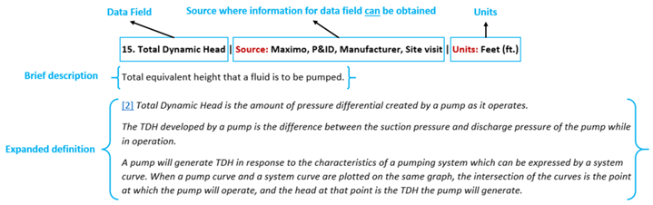
16. Total Dynamic Head | Source: Maximo,
P&ID, Manufacturer, Site visit |
Units:
Feet (ft.)
Total
equivalent height that a fluid is to be pumped.
[2]
Total Dynamic Head is the amount of
pressure differential created by a pump as it operates.
The TDH developed by a
pump is the difference between the suction pressure and discharge pressure of
the pump while in operation.
A pump will generate
TDH in response to the characteristics of a pumping system which can be
expressed by a system curve. When a pump curve and a system curve are plotted
on the same graph, the intersection of the curves is the point at which the
pump will operate, and the head at that point is the TDH the pump will
generate.
17. Inlet Size | Source: Maximo,
P&ID, Manufacturer, Site visit |
Units:
Inches (in.)
Inlet
diameter of the pump.
18. Outlet Size | Source: Maximo,
P&ID, Manufacturer, Site visit |
Units:
Inches (in.)
Outlet
diameter of the pump.
19. Impeller Diameter| Source: Maximo,
P&ID, Manufacturer, Site visit |
Units:
Inches (in.)
Diameter of
the pump impeller.
[14]
Normally,
pump vendors provide a range of impeller diameters suitable for a pump.
Impeller diameters are determined based on required head at design point. The
pump manufacturer will then trim the impeller to the required diameter.
20. Pump Casing Material | Source: P&ID,
Manufacturer, Site visit
The housing
material for the pump.
[3]
Pump
casings serve to seal off the inside of the pump to atmosphere to prevent
leakage and retain pressure. In the case of
centrifugal pumps
, they
surround the pump rotor which transmits energy to the fluid handled via
the
impeller
(s)
mounted on the rotating shaft.
In the case of
positive displacement
pumps
, they surround the rotary or reciprocating
displacement elements (e. g. one or more pistons).
21. Pump Impeller Material | Source: P&ID,
Manufacturer, Site visit
Impeller material
for the pump.
Impeller material can provide information on
wear and tear.
22. Stage | Source: Maximo, P&ID,
Manufacturer, Site visit
Number of
stages the pump has.
·
5 –
5
stage pump
·
4 –
4
stage pump
·
3 –
3
stage pump
·
2 –
2
stage pump
·
1 –
1
stage pump
·
Other –
Other
number of stages
·
N/A
[4]
What is a multi-stage pump?
A pump that contains
different stages within the piping system where force is applied to the water.
Each stage consists of one impeller as well as its accompanying diffusion
components. The term “multistage” is usually used in reference
to centrifugal pumps.
In many cases, these
pumps are referred to in terms of how many stages they contain. For example, a
pump with four stages might be referred to as a four-stage pump, or one with 10
stages would be referred to as a ten-stage pump.
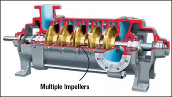
Figure
1
23. Photo of Pump Tag | Source: Site
visit
Attach a
photograph of the pump tag (1 photo).
24. Photo of Pump Body | Source: Site
visit
Attach a
photograph of the pump body (1 photo).
25. Maximo Asset Number2 | Source: Maximo,
P&ID, Site visit
Motor Maximo
Asset Number assigned by Kinder Morgan. Each asset will have its own unique
asset number.
26. Maximo Asset Tag2 | Source: Maximo,
P&ID, Site visit
Motor Maximo
Asset Tag assigned by Kinder Morgan.
This tag number will be unique for the
Terminal it’s in, but may not be a unique tag number for all Kinder Morgan
assets.
27. Manufacturer2 | Source: Maximo,
P&ID, Site visit
Manufacturer
of the motor.
28. Model2 | Source: Maximo, P&ID,
Site visit
Model of the
motor, assigned by the Manufacturer.
29. Serial2 | Source: Maximo, P&ID,
Site visit
Serial
number of the motor, assigned by the Manufacturer.
30. Frame | Source: Manufacturer, Site visit
Frame size
for motor housing.
The Manufacturer will typically assign the
motor a frame value, containing a combination of both letters and numbers.
31. Last Re-Build Year2 | Source: Maximo,
Maintenance department |
Units:
Year
This data field is not considered mandatory
Year that motor
was last re-built. If motor has not undergone any re-builds then the year that
pump was installed.
A motor is considered re-built when it comes
out of service and undergoes repairs.
32. Motor Capacity | Source: Maximo,
P&ID, Manufacturer, Site visit |
Units:
Revolutions / Minute (rpm)
Rotational
speed of the motor.
[5]
Rotational speed (also called speed, or
speed of rotation) can be quantified as the number of revolutions a rotating
system makes within a defined period of time.
33. Horsepower | Source: Maximo,
P&ID, Manufacturer, Site visit |
Units:
Horsepower (hp)
Horsepower
rating of the motor.
[6]
Equation for determining horsepower:

P = Power, hp
Q = Flow Rate, gpm
S = Specific Gravity of fluid
H = Head Height, ft.
µ
= Efficiency Coefficient
34. Power Rating | Source: Maximo,
P&ID, Manufacturer, Site visit |
Units:
Volts (V)
Electric
potential of the motor.
[7]
Single-phase motors are available in both
115V and 230V models while 3-phase motors can operate at 230V and 460V, but how
can you know which operating voltage is right for your needs?
·
115V
motors can be connected to the average household outlet, and these single-phase
motors are ideal for home uses, particularly with our
beer
pump systems
.
·
230V
motors are available in both single- and 3-phase designs and require an
electrical connection like that used to power a clothes dryer. These motors can
bridge the gap between residential and industrial grades.
·
460V
motors are ideal for more industrial settings, allowing the same amount of
power to be delivered to a motor at a reduced current. Because of their
improved efficiency, these motors are available in 3-phase designs.
35. Photo of Motor Tag | Source: Site visit
Attach a
photograph of the motor tag (1 photo).
36. Photo of Motor Body | Source: Site visit
Attach a
photograph of the motor body (1 photo).
37. Alignment | Source: Maximo, Work
Orders, Maintenance department |
Units:
Year, mils/inch, mils/inch
This data field is not considered mandatory
Proof of
alignment (Pump to Motor). Please provide the last year the Pump & Motor System
was aligned, the recommended tolerance, and the alignment value.
[8]
Motor-Pump alignment is the process of
aligning shaft centerlines between a motor and a pump. The motor is the prime
mover, transferring power to the pump by the use of a coupling. This is
probably the most common configuration of coupled machines in industry.
In this type of
alignment, the motor is almost always the moveable machine, and the pump is the
stationary machine. In almost all cases, the pump is already piped up with
suction and discharge flanges, which means it can move only slightly, if at
all.
Proper shaft alignment is achieved by moving
the motor. The motor is shimmed vertically to achieve the proper elevation to
align it to the pump, both parallel (offset) and angular. The motor is them
moved horizontally to achieve proper horizontal placement for aligning the
shaft centerlines, both parallel and angular. The motor is moved horizontally
by the use of jacking bolts, or by the use of pry bars, hammers, or other
tools.
38. Classification | Source: Maintenance
department
We are asking for two criteria regarding vibration to be examined with two drop down lists:
Hazardous (or
classified) location of area.
·
C1,D1 –
Class
1, Div 1
·
C1,D2 –
Class
1, Div 2
·
C2,D1 –
Class
2, Div 1
·
C2,D2 –
Class
2, Div 2
·
C3,D1 –
Class
3, Div 1
·
C3,D2 –
Class
3, Div 2
·
Other –
Classified,
but not listed
·
N/A –
No
classification found or needed
Hazardous (or
classified) location of asset.
·
C1,D1 –
Class
1, Div 1
·
C1,D2 –
Class
1, Div 2
·
C2,D1 –
Class
2, Div 1
·
C2,D2 –
Class
2, Div 2
·
C3,D1 –
Class
3, Div 1
·
C3,D2 –
Class
3, Div 2
·
Other –
Classified,
but not listed
·
N/A –
No
classification found or needed
[9]
The hazardous area classification system
determines required protection techniques and methods for electrical
installations in the location.
Class/Division System
The
Class/Division/Group system is based on Article 500 of the National Electrical
Code (NEC) where
Class
Class defines
the general nature (or properties) of the hazardous material
in the surrounding atmosphere.
|
Class
|
Nature of Hazardous Material
|
|
Class
I
|
Hazardous because flammable
gases or vapors
are
present (or may be present) in quantities sufficient to produce explosive or
ignitable mixtures.
|
|
Class
II
|
Hazardous because combustible or conductive
dusts
are present (or
may be present) in quantities sufficient to produce explosive or ignitable
mixtures.
|
|
Class
III
|
Hazardous because ignitable
fibers
or flyings are
present (or may be present) in quantities sufficient to produce explosive or
ignitable mixtures.
|
Division
Division defines the
probability
of the hazardous material being present
in an ignitable concentration in the surrounding atmosphere.
|
Division
|
Probability of Hazardous Material
|
|
Division
I
|
The substance referred to by class has a
high
probability
of producing an explosive or ignitable
mixture due to it being present continuously, intermittently, or periodically
or from
the equipment itself under normal operating conditions.
|
|
Division
II
|
The substance referred to by class has a
low
probability
of producing an explosive or ignitable
mixture and is present only during abnormal conditions for a short period of
time - such as a container failure or system breakdown
|
39. Foundation | Source: Maintenance
department, Site visit
The type of
foundation that is installed with the Pump & Motor System. If there is any
damage, corrosion, and/or bolts are missing please make a note of it.
·
Bolted
·
Bolted with Epoxy
·
Bolted with Grout
·
Not Bolted
·
Other
·
N/A
[10]
The
foundation of a stationary
centrifugal pump
must
be capable of absorbing the
forces
and
torques
transmitted
to it by the pump without shifting its position (see
Smooth running
); in
some cases it must also withstand forces transmitted by the associated
drive
and
piping
connected
to the pump (see
Pump nozzle load
).
The foundation's strength and vibration
behavior play a decisive role in ensuring its functional reliability.
40. Containment | Source: Site visit
Containment
is present for Pump & Motor System.
·
Yes -
containment
is present
·
Yes, to be reviewed. – containment is present, but needs to be further reviewed
·
No -
no
containment present
Containment is provided for Pump & Motor
System to capture spills or product releases.
41. Re-circulation / By-pass | Source: P&ID,
Site visit
Re-circulation
/ bypass is present for pump system:
·
Yes –
Re-circulation back to the pump
·
Yes –
Re-circulation back to the source
·
Yes –
Bypass the pump
·
No –
Re-circulation / Bypass not present
Ability to continue product movement through
a secondary pipeline around pump.
42. Reducer Proper Installation | Source: P&ID,
Site visit
Proper installation
of reducer:
·
Yes –
Properly
installed
·
No –
Not
properly installed
·
N/A –
Not
applicable
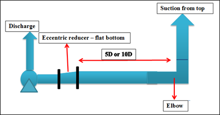
[11]
Eccentric
reducer
is recommended for
horizontal flow to the pump. This configuration prevents are pocket
accumulation at the upstream end of the reducer. Concentric reducer is recommended for the vertical inlet (suction)
piping or horizontal installations where there is no potential for air vapor
accumulation.
When the source of
supply is above the pump, then the eccentric reducers must be placed with the
flat side down. When the source of supply is below the pump, then the
eccentric reducers must be placed with the flat side up.
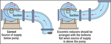
Figure
2
In case of long horizontal pipe runs, air pockets are avoided by
installing the eccentric reducer with the flat side up.
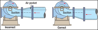
Figure
3
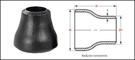
Figure
4
- Concentric Reducer
43. Intake Line Fittings Allowance | Source: Calculation | Units: Inches (in.)
Calculation
(Pump inlet diameter * 5).
[11]
Pumps, and especially centrifugal pumps,
work most smoothly and efficiently when the fluid is delivered in a surge-free,
smooth, laminar flow. Any form of turbulence reduced efficiency and increases
wear and tear on the pump’s bearings, seals and other components.
ANSI/HI 9.8 American
National Standard for Pump Intake Design (P21,1998)
states, “There shall be no flow disturbing fittings (such as partially open
valves, tees, short radius elbows, etc.) closer than five suction pipe
diameters from the pump. Fully open, non-flow disturbing valves, vaned elbows and reducers are not considered flow
disturbing fittings.” This standard eliminates any reference to the possible
flow distribution that could be generated by the reducer.
The concept is simple though, ensure stable and uniform flow onto the
impeller eye. This results in fewer pump failures over the life of the pump due
to vibration caused by flow induced turbulence.
Figure
5
In case several improperly specified parameters
come into the equation (e.g. viscosity changes etc),
then it would be prudent to install as many as ten suction pipe diameters of
straight piping next to the reducer inlet flange. A number ranging between five
(5) to ten (10) suction pipe diameters of straight pipe run is typically the
recommended value in published technical literature.
Sometimes
due to space constraints, it’s just not possible to make provision for a
sufficient settling distance in the pipework before the pump. In these cases,
use an inline flow conditioner or straightener.
44. Intake Line Fitting (Distance from Pump) |
Source:
Site visit
Units:
Inches (in.)
Actual
distance from pump inlet to nearest line fitting. Please refer to 43. Intake Line Fittings Allowance for
educational description.
45. Photo of Pump/Motor System| Source: Site
visit
Attach a
photograph of the Pump & Motor System (1 photo).
46. Vibration | Source: P&ID, Site
visit
We are
asking for two criteria regarding vibration to be examined with two drop down
lists:
Vibration
sensors are properly installed for Pump & Motor System:
·
Yes –
Installed
·
No –
Not
installed
Vibration
detected on Pump & Motor System
(If “Yes”, please
explain how it was measured and
documented in the notes section
& please submit attachment)
:
·
Yes, Documented and Measured
·
Yes, Measured
·
No
If you have
responded “yes” to the second drop-down list (Vibration detected on Pump &
Motor System), please explain how it
was measured and documented in the
notes
section & please submit attachment. Please identify the data field
number “46.”.
[12]
Vibration monitoring of critical and auxiliary
pumping systems helps improve machine reliability, safety and production
capability. Pumps produce vibrations indicative of running condition, incipient
faults and component failure. These vibrations appear at specific frequencies
across a wide spectrum.
Industrial
piezoelectric accelerometers provide the dynamic and frequency ranges required
for complete pump monitoring. Vibration is an integral part of an effective,
predictive maintenance program, enabling the early detection of failure modes
such as impeller erosion, pump imbalance, shaft looseness, coupling problems
and cavitation. The vibration sensor that is for the application will depend on
the frequencies of interest and the type of pump being monitored.
47. Bearing Temperature Thermocouples | Source: P&ID, Site Visit
Bearing Temperature Thermocouples are properly installed for
Pump & Motor System.
·
Yes –
Installed
properly
·
No –
Not
properly installed
[13]
Condition monitoring has proven important in
the installation and maintenance of all types of turbomachinery throughout the
past 30 to 40 years. Babbitt bearing temperature is primarily important because
bearings are the critical links between the rotating and stationary components
in a machine. If temperatures are taken in the correct location with respect to
the direction of bearing load, to direction of shaft rotation and to the
distance of the tip of the sensor from the bearing running surface, then
Babbitt metal temperatures can be the best indicators of a bearing's operating
condition.
Data analysis
from many bearing tests, prototype turbomachinery tests and day-to-day
operation has pinpointed the locations of greatest sensitivity for installing temperature
sensing probes. In most bearing applications, the current state-of-the-art
technology uses some type of electrically variable tip at the end of a current
conducting set of wires. The wires provide a flexible connection to the outside
of the bearing while the sensor tip is engineered to the smallest practical
size for insertion into the bearing.
48. Flow Switch |
Source:
P&ID, Site Visit
Flow switch, Flow Indicator Transmitter (FIT), Pressure Indicator Transmitter (PIT) is installed downstream of the Pump & Motor System.
·
Yes –
Installed
·
No – Not Installed
49. Emergency Shutdown System | Source: P&ID,
Site Visit
Emergency
Shutdown System is properly installed for Pump & Motor System.
·
Yes – Installed
·
No –
Not
installed
[14]
The purpose of an Emergency Shutdown System
(ESD) is to provide a fail-safe independent control system that can shut down a
station and isolate it in the event of a pipeline rupture or a fire at the
station.
The ESD system
overrides any operating signals from the station or local controls and its
design therefore, needs to meet the requirements of both the regulatory regime
and the owner’s own design philosophies and criteria.
The ESD is the last line of defense to shut
down a station and must be able to perform its function even if the station has
lost normal power supply, has lost the ability to communicate with SCADA or in
the case of local control, system failure
.
50. Leak Detection System |
Source:
SCADA, Site Visit
Leak
detection system is properly installed for the Pump & Motor System.
·
Yes – Installed
·
No –
Not
Installed
Please
answer yes if there is a leak detection system installed for the Pump &
Motor System. Some examples of leak detection systems include Plan 65B Seal Leak Pot, HCD
Point Detector, and Slick Sleuth Detector.
51. Fire Protection System | Source: SCADA, Site Visit
We are
asking for three criteria regarding fire protection system to be examined with
three drop down lists:
Fire
protection system is installed for or near the Pump & Motor System.
·
Yes –
Installed
·
No –
Not
Installed
Proximity of
fire protection systems to Pump & Motor System.
·
Within 10 Feet
·
Between 10 and 50 Feet
·
Greater than 50 Feet
·
N/A –
Not
Installed
System
response
·
Automated System
·
Manual System
·
N/A –
Not
Installed
First, we want to know if there is a fire
protection system installed for or near the Pump & Motor System. If so, we
would like to know how close the fire protection systems (fire monitors, fire
truck hook ups, etc.) are to the Pump & Motor System.
52. In-service Product(s) | Source: Operations
department
Product that
flows through Pump & Motor System (If multiple, please separate by comma).
53. Max Flow Rate Desired | Source: Commercial
dept., Operations dept. |
Units:
Gallons / Minute (gpm)
Numerical
representation of the maximum desired flow rate.
This value is typically set by the
Commercial & Operations Department.
54. Actual Flow Rates | Source: Operations
dept., SCADA | Units: Gallons /
Minute (gpm)
Numerical
representation of the actual flow rates.
This value is the current operating flow
rate through the pump. This value can be gathered by Operations or by SCADA.
55. Maintenance History | Source: Maximo Report
Proof of Maintenance History. Please provide:
1. Total Corrective Maintenances (CM)
2. Year of last Corrective Maintenance (CM)
3. Preventive Maintenance (PM) assigned to pump
·
Yes
·
No
·
NA
References
[1]
Rotational
speed | KSB. (n.d.). Retrieved May 11, 2020, from
https://www.ksb.com/centrifugal-pump-lexicon/rotational-speed/191072
[2]
Total
Dynamic Head (TDH) Definition. (n.d.). Retrieved May
11, 2020, from
https://www.introtopumps.com/pump-terms/tdh-total-dynamic-head/
[3]
Germany, F.,
& Ksb Ag. (n.d.). Pump
casing. Retrieved May 11, 2020, from
https://www.ksb.com/centrifugal-pump-lexicon/pump-casing/191326/
[4]
Multistage Pumps. (n.d.).
Retrieved from
http://www.pumpscout.com/all-pump-types/multistage-pumps-ptid96.html
[5]
Germany, F.,
& Ksb Ag. (n.d.). Flow
rate. Retrieved May 11, 2020, from
https://www.ksb.com/centrifugal-pump-lexicon/flow-rate/191086/
[6]
Hydraulic
Pump Horsepower Equation - Engineers Edge. (n.d.).
Retrieved May 11, 2020, from
https://www.engineersedge.com/motors/pump_power_equation.htm
[7]
Which Motor
Voltage Do You Need? (2016, January 18). Retrieved May 11, 2020, from
https://www.marchpump.com/blog/which-motor-voltage-do-you-need/
[8]
Motor-pump
Alignment. (n.d.). Retrieved May 11, 2020, from
https://vibralign.com/resources/concepts/motor-pump-alignment/
[9]
Hazardous Areas Classification - North America. (n.d.). Retrieved from
https://www.engineeringtoolbox.com/hazardous-areas-classification-d_345.html
[10]
Pump
foundation | KSB. (n.d.). Retrieved May 11, 2020,
from
https://www.ksb.com/centrifugal-pump-lexicon/pump-foundation/191602
[11]
Theprocesspiping
. (2018, August 7). Pumps Suction Piping
- Eccentric Reducers & Straight Lengths. Retrieved from
https://www.theprocesspiping.com/pumps-suction-piping-eccentric-reducers-straight-lengths/
[12]
Klubnik, R., Meggitt Sensing
Systems, Mss, & Wilcoxon Research. (2011,
December 17). Pump Vibration Monitoring Basics. Retrieved May 11, 2020, from
https://www.pumpsandsystems.com/pump-vibration-monitoring-basics
[13]
Temperature
as Indicator of Bearing Operating Condition ... (n.d.).
Retrieved May 11, 2020, from
https://www.pumpsandsystems.com/temperature-indicator-bearing-operating-condition
[14]
Mohitpour
, M., Yoon, M., & Russell, J. (2012). Hydrocarbon Liquid
Transmission Pipeline and Storage Systems - Design and Operation. Asme Press.
Figures
Figure 1 - Multistage Pump
Guide. (n.d.). Retrieved from
https://www.castlepumps.com/info-hub/multistage-pump-guide/
Figure 2 -
Theprocesspiping
. (2018, August 7). Pumps Suction Piping - Eccentric Reducers
& Straight Lengths. Retrieved from
https://www.theprocesspiping.com/pumps-suction-piping-eccentric-reducers-straight-lengths/
Figure 3 -
Theprocesspiping
. (2018, August 7). Pumps Suction Piping - Eccentric Reducers
& Straight Lengths. Retrieved from
https://www.theprocesspiping.com/pumps-suction-piping-eccentric-reducers-straight-lengths/
Figure 4 –
Concentric Reducer. (n.d.). Retrieved from
https://www.shikharsteel.com/concentric-reducer-manufacturer-supplier.html
Figure 5 -
Theprocesspiping
. (2018, August 7). Pumps Suction Piping - Eccentric Reducers
& Straight Lengths. Retrieved from
https://www.theprocesspiping.com/pumps-suction-piping-eccentric-reducers-straight-lengths/
